Physics
Theoretically Applied Electrodynamics
Some thought's on the "Russian Capacitors"
...with regard to the newly planned capacitor bank...
| 1.
Analysis of the pulse capacitors 2. Discharge of the entire capacitor bank 3. Is it possible to use the capacitor at I(max(>3kA with a lower pulse rate than R=12/min? 4. Discharge of the entire capacitor bank- pulse magnetic forming/welding 5. Discharge of the entire capacitor bank- Exploding wires .. |
Abstract: |
|
| Max
Bigelmayr, October 2011, April 2013 |
 1.
Analysis of the pulse capcitors
1.
Analysis of the pulse capcitors
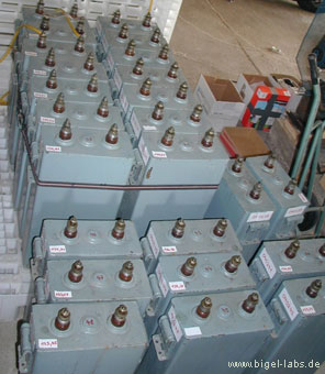
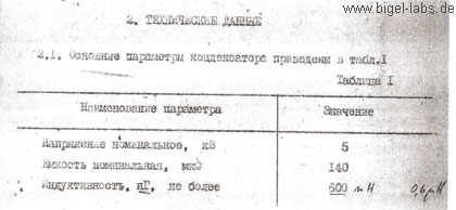
´We have 36 pulse capacitors to our disposal. After translating the original data sheets from russian into english, the following information was given:
Datasheet of the capacitors |
 |
Within the capacitor bank, individual electrical condensers will be
connected to one another.
To analyse the discharge behaviour, I programmed a special "Capacitor-Analysing-File".
With the help of this program, I was able to solve the differential-equation-system
by using Runge Cutta Algorithms, which provided me with the numerical
discharge curves, concerning U(t), I(t), A(t).
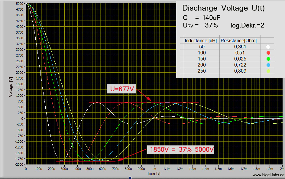
Graph 1: The parameters
L and R have been specifically chosen, so that all curves have a reversal
voltage of -1850V, which is equal to a log. Dekr.=2
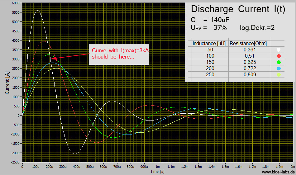
Graph 2: Currents
I(t) with the same parameters as before
I tried to find the curve with Imax= 3kA and a reversal voltage of 37%. It´s a CLR circle with C=140uF, L=175uH and R=0.65Ohm.
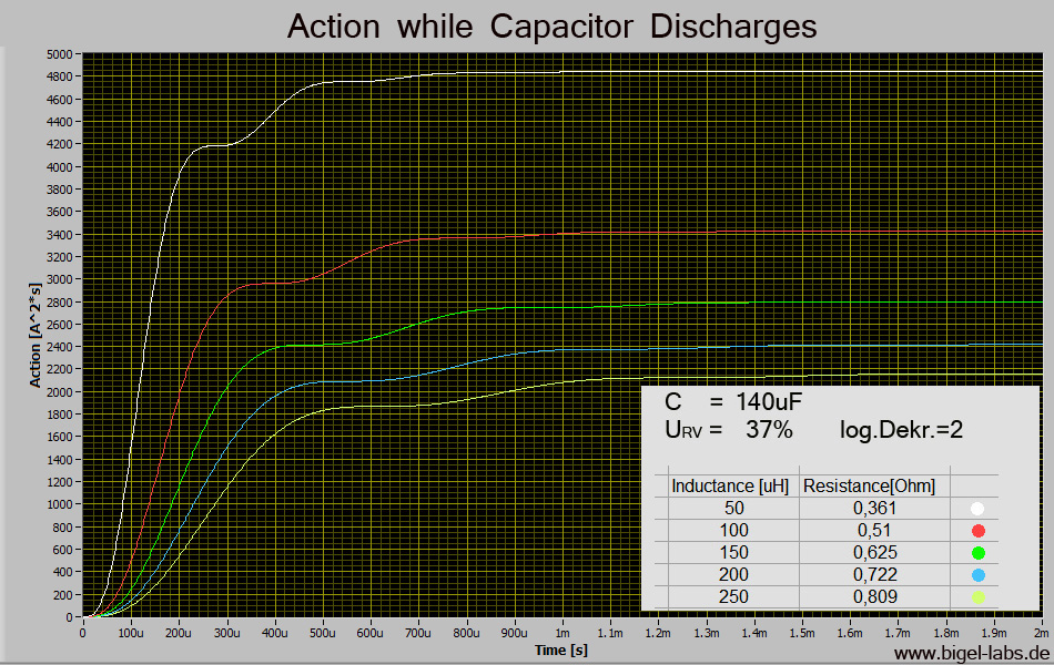
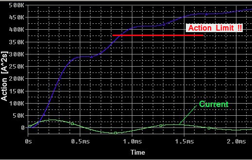
Graph 3:
Action
curves A(t) with the same parameters as before
2. Discharge of the entire capacitor bank
The russian capacitors ought to be used within a new capacitor bank:
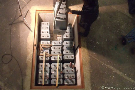 |
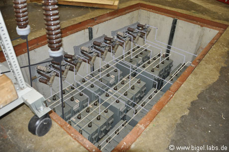 |
| Installation of the Capacitor bank |
Let us assume that a pulse capacitor bank network, with n identical capacitors
which are joined together in parallel is assembled.
If we neglect the inductance between the capacitors, we can assume that
I1=I2=I3....In.
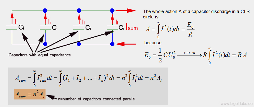
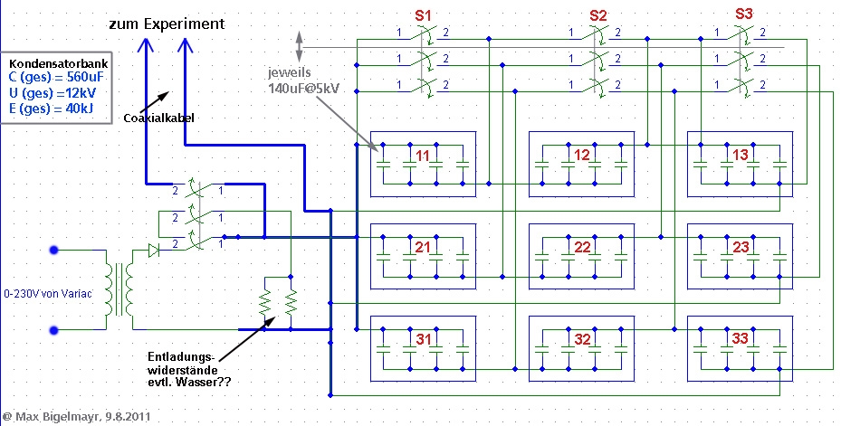
In the planned capacitor bank, we will connect 12 capacitors
in parallel (view schematic diagram above). Prior to this we found out
that the maximum Action A for one capacitor is 2600A^2s. Now it is very
easy to calculate Asum:
![]()
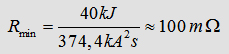
The total capacitance of the capacitor bank will be situated at 560uF.
The stored energy of 40kJ at 12kV, allows for the calculation of the minimal
load resistance permitted during pulse-experiments. In general we can
say:
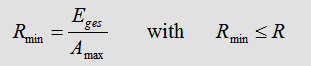
For the used capacitor bank Rmin is:
In the following step it is possible to simulate different discharges
of the capacitor bank with a defined R=100mOhm:
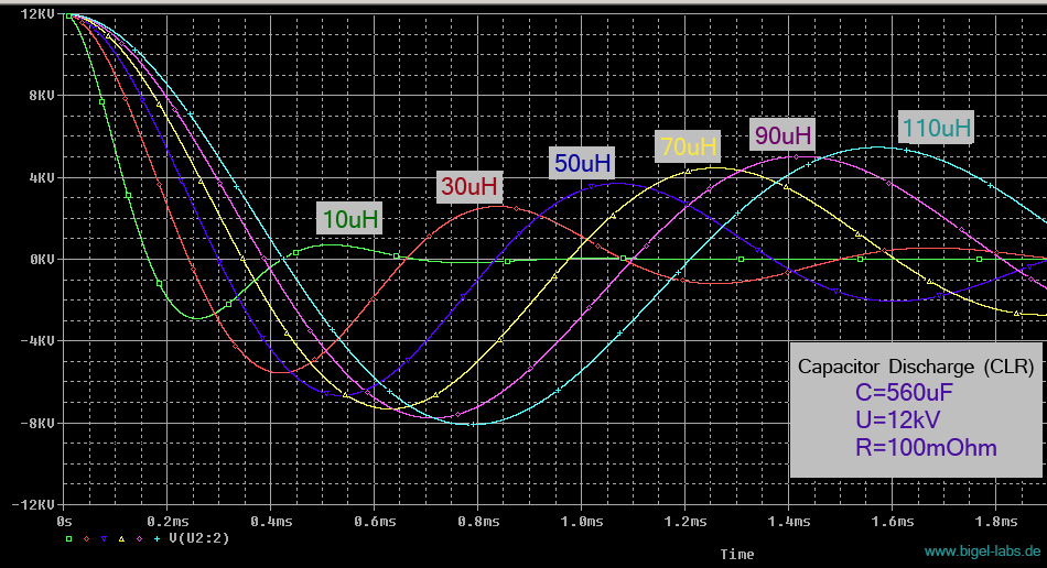
Graph
4: Discharge Voltage Uc(t)
of the entire capacitor bank with a different line inductance and
a load resistance of 100mOhm.
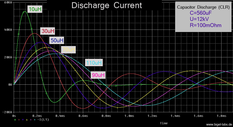
Graph
5: Discharge current Isum(t)
of the entire capacitor bank with a different line inductance
and a
load resistance of 100mOhm.
3. Is it possible to use the capacitor at I(max(>3kA with a lower pulse rate than R=12/min?
 Earlier
we calculated the maximum Action Integral of one of the
Earlier
we calculated the maximum Action Integral of one of the
russian capacitors: A=2600A^2s. With this value in mind we are able to
reflect on the internal fuse within the capacitors. Let us assume that
it is a specific type of iron wire. The wire should be the critical part,
which warms up during discharge. Every discharge-pulse will cause for
the wire to heat up. If the capacitor is used every 5 seconds, in a pulse-performance
mode (pulse rate of 12pulses/min), the capacitor is charged and discharged
in sudden succession. The action integral A(charge) regarding the charge,
is precisely equal to the action integral A(discharge) concerning discharge.
.jpg)
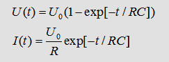
First of all the capacitor is charged up within 5s. We could use a source
of voltage with a current of U0=5kV. The voltage and current are described
by the following:
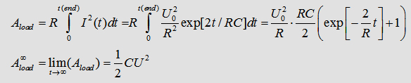
It is fairly straight forward to calculate the Action-integral and the
limes for time-> infinity:
However we haven't got an endless amount of time to disposal. Therefore
a typical load circle/cycle?? could be a voltage source with a current
of U=6kV, followed by an Ohm-resistor. Thus the voltage will reach precisely
5kV after 5s.

4. Discharge of the whole capacitor bank- pulse magnetic forming/welding
[ supplement April 2013]
In 2006 I made some
pulsed
power experiments with spiral
coils. With the capacitor bank KB1-KB2 I achieved discharge pulses
similar to the following:
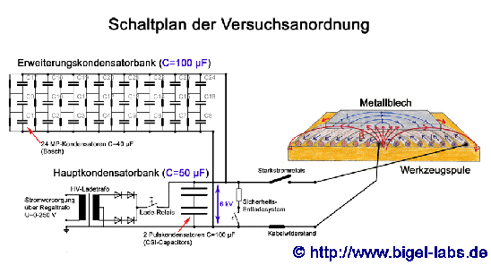 |
 |
| Schematics of the capacitor bank KB1-KB2 | Capacitor voltage U(t) while a discharge with Spiral coil FL2 |
One may try to simulate the discharge behavior with PSpice to get a similar voltage curve U(t). I tried many different Schmematics and values to describe be measured curve U(t). One possible circuit is this:
 |
 |
| PSpice Simulation of the capacitor bank KB1-KB2 | Simulation of Capacitor voltage U(t) and Discharge Current I(t) with Spiral coil FL2 |
In this simulation the current grows up to around 10,5kA peak.
If we use the large 40kJ capcitor bank instead of the "small KB1-KB2"
one may assume a line inductance of around 20uH. Let´s use the coil
FL2 and subsitute the capacitance with 560uF and the voltage source with
12.000V. In this case the circuit becomes:
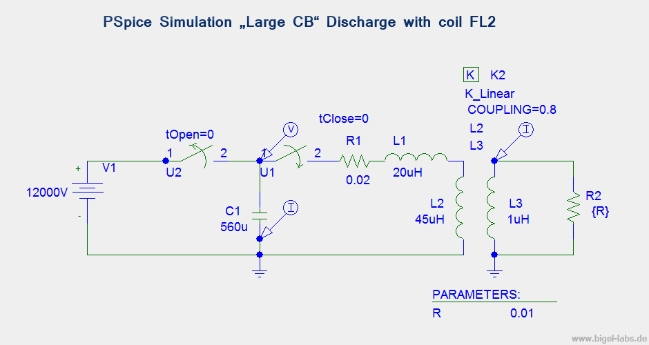 |
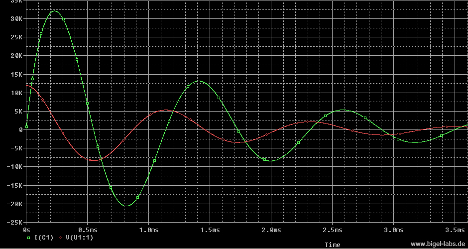 |
| PSpice Simulation of the Large Capacitor Bank (LCB) | Simulation of Capacitor voltage U(t) and Discharge Current I(t) with Spiral coil FL2 |
You may realize the bad damping while the discharge. The reversal voltage
is around 8kV, which is equal to 8kV/12kV=2/3 ~> 66% One may also calculate
the quality factor Q with the voltage reversal %RV:
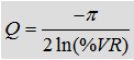
With RV=66% the quality factor becomes -0.37. The stresses on capacitors
caused by reversal include increased electric fields in the dielectric,
increased electrical losses, heating in the dielectric and heating in
the conductors. In many studies GENERAL ATOMICS ENERGY PRODUCTS
found out that the life time of capacitors may be pushed by derating the
voltage reversal. As we calculated in the beginning the nominal voltage
reversal of the russian capacitors is around 37%. For lifetime reasons
the capacitor bank will be only discharged at a voltage level of 80%Umax(nom).
So each individual capacitor will be charged up to only 4kV instead of
5kV. Let´s discuss how this technic does influence the lifetime
coefiicient.
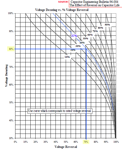
With the graph on the left sight it´s possible to find a new reversal
voltage for a specific capacitor if you know the reveral voltgage by nominal
voltage use. In our case we have got a nominal Voltage Reversal
of 37% at 5kV. So we will get a "new reversal voltage" if we
only charge up to 4kV, which is a Voltage Derating of 80%. In
this case we get a new Voltage Reversal of around RV=70%. That´s
really a nice value, isn´t it?? ;-)
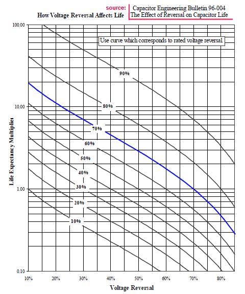
With the graph on the right we may existimate the Life Expectancy Multiplier
(LEM). With the coil FL2 (RV=66%) the LEM is around 1.2-1.3, so that we
would get an "pushing life factor".
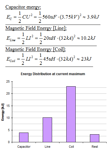
The coil inductance (L=45uH) is just around two times the line inductance
(L=20uH). While the discharge the energy may only/manly be absorbed in
the coil. While the maximum current of I=32kA we have got a capacitor
voltage of around 3.75kV. At this time the energy distribution is:
 |
 |
| Simulation
of the Action Integral while
the discharge As we saw before the voltage reversal of around 66% is not really hard to the capacitors. But what about the Action integral? It´s growing up to high!!
|
There are three possible solutions:
1.) Using of "high inductance coils"
We could use high inductance coils with L >100uH to maximize
the quotient L(coil)/L(ges). This will give a much better damping and
low voltage reversal. The disadvantage is a low currentraise dI/dt. The
metals we want to form won´t be accelareted that fast with "high
inductance coils".
2.) Using of parallel diodes
We could use high voltage high current diodes.
Disadvantage: We haven´t got such diodes. Maybe it is possible
to use cheap high voltage diodes (with low current rates)
and vaporize them while the discharges.
3.) Using of vaporization coils
By using coils with a low wire diameter ist´s possible
to find a perfect wire diameter, so that the coil will vaporize just after
the first half wave. In this case the capacitors don´t have to absorb
all the low damping oszillation energy.
 Simulation
with "high inductance coils"
Simulation
with "high inductance coils"
In 2006 I also used a three
layer spiral coil with 42 roundings and a inductance of around 100uH
(picture on the right).
A simulation with this inductance gives us the followinhg discharge characteristic...
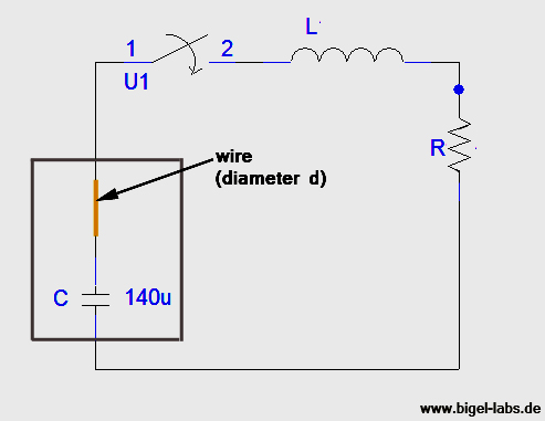
5. Discharge of the entire capacitor bank- Exploding wires
The discharge behaviour of capacitor banks, through a variable resistor
R(t) is a fairly complicated topic. To understand this phenomena, I programmed
a tool with which I am able to input and analyze all the required data
(capacitance, voltage, load inductance, wire material, diameter, length...)
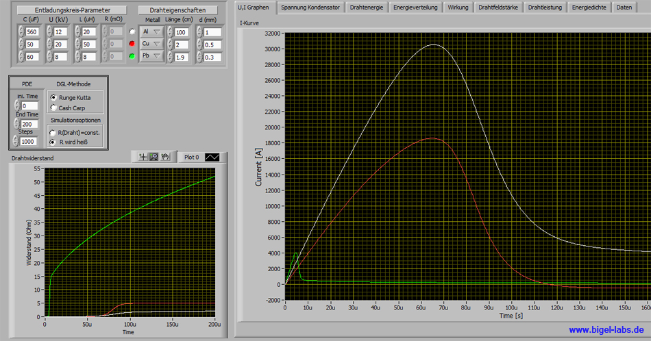
| With the program I can
simulate: - discharge currents - discharge voltages - field strenght inside the wire - energy density in the wire - absorbed energy in the wire - power curves - periodic times - Action integral .....................................and a lot moore.... |
The coupled differential
equation systems are solved by using Runge Kutta or Cash Carp algorithms. The new capacitor bank should be used with an Action-integral of less than 375.000A^2s. With the give simulations, one is able to discover the optimum parameters concerning such a pulse discharge.
|
|
|
First
theory, after that experiments....... |
Simulation results for these Parameters:
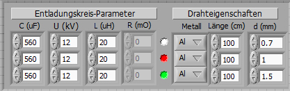 |
.....Selecet the graphs you want to watch with the mouse..... |
||||||
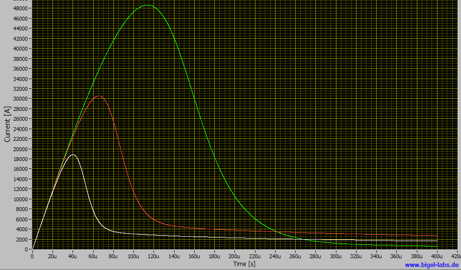
|
|||||||
In all three cases the action integral is lower than 375kA^2s. With a
diameter of 1.5mm, the action integral would achieve 225kA^2s.
In real experiments the wire vaporizes, resulting in a very rapid breakdown
of the current. Most experiment's will occur as puls-discharges. During
the first pulse the wire is heated up. The resistance of the wire suddenly
prevents a discharge. This occurrence is known as a darkness brake. Following
this phenomena, the metal boils and "metal gases" leave the
wire in a radial manner. This resulting plasma surrounding the wire, will
initiate a second discharge pulse. In general one can assume that all
these effects will not create a larger action integral than calculated
in the simulation above. Therefore such experiments are possible without
the fear of killing the capacitors through such discharges.